Made in America:  A Different Take on Metal 3D Printing

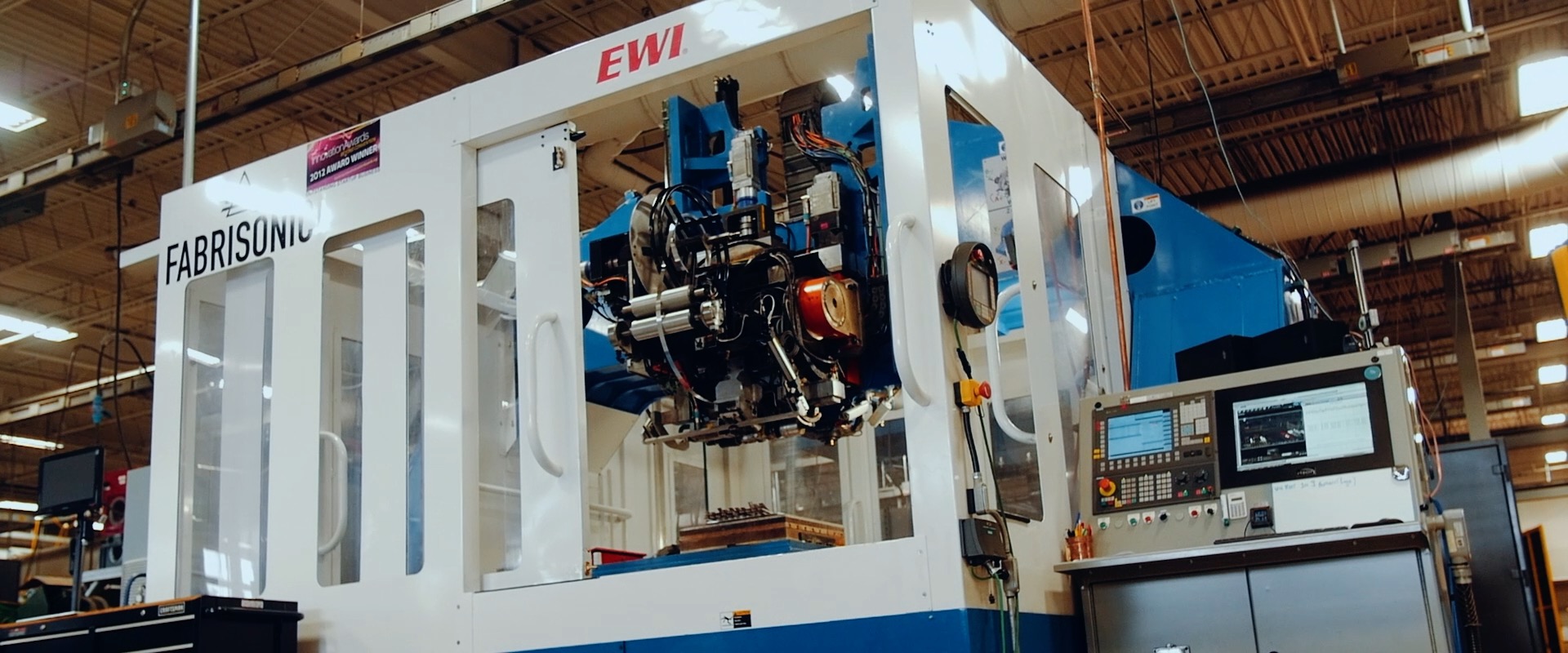
Fabrisonic recently had the pleasure of hosting the crew from Made in America to talk about metal 3D printing. These journalists travel the country and document the dynamic of American manufacturing, from industrial luggage at Pelican to metal 3D printing at Fabrisonic.  All of the diverse manufacturing companies have one thing in common, they all make their products here in the USA.

IEN-Fabrisonic-made-in-america

Check Out Our Made in America Feature Here!

During their stay, we talked about many of the factors that make Fabrisonic’s 3D printing process unique:

  • Low Temperature Welding – Ultrasonic welding happens near room temperature with no changes in microstructure or metal temper
  • Hybrid Approach – All Fabrisonic systems have both an additive stage and a subtractive stage meaning all surfaces, internal and external, have CNC quality surface finish and accuracy.
  • Dissimilar Metals – The solid-state nature of UAM allows all Fabrisonic systems to weld dissimilar metals within a single part without adverse metallurgical reactions.
  • Embedding Electronics – The hybrid approach coupled with the low temperature welding allows SonicLayer systems the ability to embed electronics or sensors anywhere in solid metal parts
  • Common Feedstocks – UAM systems utilize commercially available metal foils


Thanks to the crew from Made in America.  It was a great visit!

New Call-to-action


‘Smart Baseplate’  – Measuring stress in PBF baseplate

Fabrisonic’s patented low-temperature Ultrasonic Additive Manufacturing (UAM) process utilizes ultrasonic welding to 3D print metal parts.  Although our process does not use powders, we have lots of friends in industry that use powder based processes.  Read “Not ALL 3D Printers Use Powder” for a more in depth break down of the difference between UAM and powder bed fusion.  One of the biggest complaints we hear from our powder brethren is consternation around build plates:

  • Parts can debond or delaminate from the build plate during printing, which can be difficult to detect since the part is buried in powder.
  • Build plates distort due to build up residual stress.
  • Build plate bolts break from excess residual stress during a build.
  • We don’t understand how stress builds up around individual parts during a build leading to distorted final parts.

During one such conversation with our colleagues at EWI, he stated, “How can we measure the loads going through the build plate?”  Since Fabrisonic was working currently on embedding strain sensors in aerospace parts, we suggested that we 3D print a build plate with embedded sensors.   And thus began the journey to build a ‘smart baseplate’ or ‘smart build plate’.

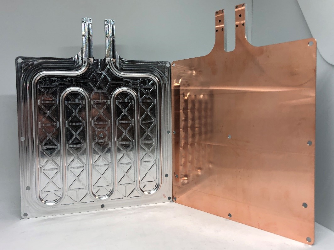
Fabrisonic teamed with EWI (PBF research) and Luna Innovations (Fiber Optic Sensors) to design and build an instrumented PBF build plate for the Defense Logistics Agency (DLA) under a Phase I STTR.  Fabrisonic used its solid-state 3D process to print a plate with a single embedded fiber optic sensor.   The fiber optic was embedded with a specific undulating pattern that allows resolving the strain across the entire build plate.  The team put the smart baseplate in EWI’s PBF machine and attempted a build that included ‘problematic’ features.   From this initial build the team found that the device picked up significantly more information than just bulk stress state:

  • Resolution and scan rate were high enough to actually discern the scan strategy of each layer.
  • Defects showed up as large compressive strains forming early in the build at localized points.
  • Slow delamination of a specific feature could be seen in the data although the recoater blade never hit the build.

The video above shows true strain-time plots resolved in the x-y plane (left) and the raw data along the length of the fiber (right).   These colorful strain-time histories easily communicate what is happening in the build.   However, further data slicing can provide a deep understanding of the quality of the build:

  • Analyzing individual ‘pixels’ for sudden vector changes provides tell-tale signs of many build issues.
  • Comparing time histories of adjacent pixels also highlights problems in the build.


Figure 1 – As a crack forms and propagates it is normal to see a transverse compression to form at the point of separation (left).   Strain vector changes also highlight certain flaws (right).

Based on the preliminary results, the team feels that this approach could be used to monitor quality during PBF builds:

  • For series production, data can be compared between a known ‘good’ baseline and subsequent serial numbers.
  • For low volume, build flaws can be identified as they happen allowing the operator to do a full abort, saving powder and machine time.
  • For multi-part builds, build flaws in a single part can be seen allowing the operator to abort that feature before it affects others.

The team has recently been awarded a PH II STTR with the DLA to further explore this technology.   We hope to expand the capabilities by refining data mining techniques and embedding more sensors.  For instance, by embedding sensing fibers at two heights we can resolve both planar stress and moments.

New Call-to-action